LEDs + Lighting
How Long Do LEDs Last? Part II
Published
14 years agoon
In my previous column, I said today’s high-power (HP) and high-brightness (HB) LEDs are more difficult to manufacture — and don’t endure as long — as low-power (LP) LEDs, because the advanced group requires higher operating currents, which accelerates lamp aging. Directing an elevated injection current into an LED chip causes relatively higher junction temperature (TJ), and, because heat must be conductively removed from the LED chip’s backside, such an increase requires a sophisticated, thermal-management system.
The complexity of LED lamp thermal management is a major reason why LEDs haven’t yet become mainstream in the illumination industry.
To come into common use, LED-based, regular household lighting and signage applications need consistently higher — and less costly — performance, sans sophisticated systems or end-user adjustment.
Without successful thermal management, LEDs’ light output, color and efficacy quickly degrade. However, LEDs mounted in sophisticated, electronically controlled, interpretive systems (such as those found in electronic displays) degrade at a much slower rate.
We’ve all seen electronic or electrical gadgets’ LED indicator lights last a long time, and this endurance causes the belief that LEDs last almost forever. However, indicator lamps need only a few milliamps to operate, and diminishing light output isn’t a concern.
General-illumination and signage lamps require several hundreds of lumens, from limited-size sources, and also demand certain luminance levels, as well as color quality and uniformity. And, certain high-end applications, such as automotive headlights, need even higher lumen output and luminance; thus, sophisticated, thermal-management systems are needed to ensure longevity with high optical quality.
For example, Osram Sylvania has produced its OSTAR brand, LED headlights for Audi’s $75,000 A8 sedan. Osram says the headlights have a minimum life of 7,000 hours. While this lifespan seems adequate for this application, typically, less-bright LED lifespans are much longer.
Thermal design and management
Fortunately, the solid-state industry takes thermal challenges seriously. It’s now producing brighter and bigger LEDs that can carry more electrical power before suffering burnout. The progress stems from increased demands for HB-LEDs, and, also, brighter, large-area LEDs (for numerous applications, including signage) have spurred manufacturers’ engineers to pursue ongoing, technological improvements.
To conquer thermal problems, LED engineers must resolve how to reduce TJ dependence on the operating (drive) current, which, in turn, will lead to increasing LED lamp lifespan.
The junction temperature is measured at the diode’s active region (the compound semiconductor material in inorganic LEDs), which is the hottest point in the entire LED module or luminaire, if the module is integrated in a luminaire.
No doubt, future design improvements in semiconductor epitaxial quality, LED-device design, metallization and other, related processes will lead to substantially lower TJ dependence on operating current. A lower operating current significantly increases LED lamps’ lifetimes; lower currents also simplify thermal management and reduce design and manufacturing costs.
Stronger TJ dependence in drive current may lead to faster and greater degradation of color quality, due to wavelength shifting, which becomes more pronounced over time.
When higher illumination is preferred, it’s often better to increase the number of individual LEDs (provided there’s space) and, simultaneously, reduce the drive current to generate less heat (see ST, April 2009, page 58).
Every LED module, due to its particular design, material properties and fabrication style, has an inherent maximum TJ, labeled TJMAX. Overdriving this figure will lead to catastrophic failure. Oppositely, the best injected current is when the TJ is 20% (typically) below the TJMAX. Additionally, thermal management must apply to the entire fixture or enclosure, because limiting the maximum operating temperature of all module components duly applies to the entire luminaire. You can also extend an LED lamp’s lifespan by allowing significant heat removal from the junction area.
Without thermal management, an LED chip continues to heat up and, over time, the TJ will exceed TJMAX, which leads to burn-out.
When sophisticated thermal management incorporates both structural design, packaging and material technology, a higher TJ can be tolerated — if an efficient thermal conduction path (heat sink) is created between the LED junction area and the circuit board assembly upon which it is mounted.
However, such designs will increase the module and luminaire cost; it almost always increases the luminaire size. Expensive modules and sophisticated thermal management creates higher unit costs for signmakers, but the cost might diminish if the LED modules generated less heat.
Minimize resistance
Effective thermal-management designs call for an efficient, heat-conduction path that minimizes thermal resistance (or increases thermal conductance) along a path from the junction to the die submount — the first heat sink — and continues to the printed circuitboard (PCB), the second heat sink, upon which the die submount is installed.
Such a system also needs to integrate appropriate, thermal-conductive materials (that is, high, thermally-conductive substrates such as alumina and metal-core PCBs, and good thermal epoxy or grease), packaging techniques (good solder joints), and substrate geometry that may include thermal (via holes) and flat mating surfaces.
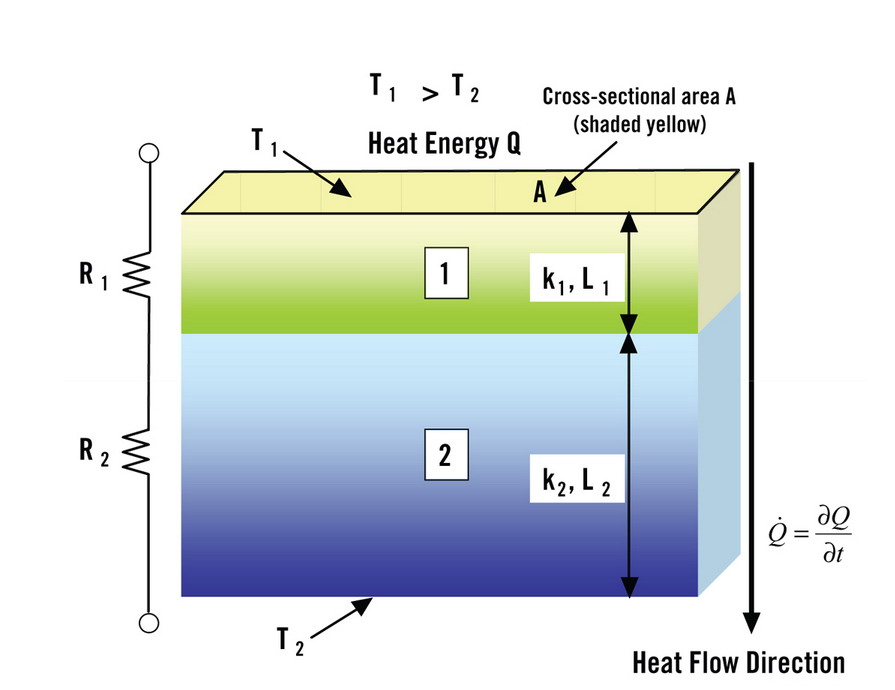
Thermal resistance is defined by the resistance of a material to heat conduction, which depends on the materials’ inherent conductivity property (k) as well as its length and cross-sectional area. It also relates to the temperature difference between the two, adjacent surfaces, where heat transfers from one to the other along a perpendicular path, thus, dividing the heat-energy flow rate.
Both definitions are analogous to electrical resistance. The unit of thermal resistance is the degree Centigrade per watt (°C/W), where W is thermal wattage or power. In an LED, generated, thermal power equals injected electrical power (i.e., voltage times current) driven into the LED, minus the emitted optical power. This equation shouldn’t be mistaken for electrical power when calculating the thermal resistance in an LED module. In more-efficient LEDs, the generated thermal power is lower than that found in a less-efficient LED, even when the same amount of electrical current is injected.
In the solid-state lighting (SSL) industry, it’s common to use a model similar to that shown (Fig. 1), where material 1 is the LED chip, material 2 the chip submount (the first heat sink) and, sometimes, there’s a material 3 for the PCB (second heat sink). The junction temperature TJ is analogous to T1; T2 is analogous to the temperature of the first heat sink; similarly, add T3 for the PCB, the bottom of which is usually the ambient temperature when a stand-alone LED module is tested.
This model is used along with the measured values of forward voltage, T1, and T2 (and perhaps T3) to determine TJ of an LED. Use caution, however, to not mix thermal resistance with electrical resistance and thermal power with electrical power.
A more rigorous way of determining TJ is to use a full, 3-D, finite element or finite difference method to model the thermal behavior (i.e., solving a heat-wave equation) of an LED when a constant current is injected into it, with all of its surrounding components functioning.
Advertisement
Ambient temperature
Also, be mindful that thermal resistance is a function of ambient temperature, because k and the geometric parameters all change with temperature. The modeling results should be used in conjunction with as many measured parameters as possible, under different ambient temperatures.
The science behind accurately determining TJ and TJMAX are quite complex and time consuming. It requires an iterative effort between rigorous modeling, or calculations, and extensive measurements of various LED parameters. The modeling results should be used in conjunction with test results, but under different ambient temperatures, to determine TJ. Multiple iterations will ensure the convergence of a convincing TJ value.
Quantifying relationships between TJ, TJMAX and optimal drive current for various LEDs modules to be used in the sign and illumination industries and, ultimately, designing brighter and more efficient LED modules, are some subjects of my upcoming research and development plans.

SPONSORED VIDEO
Introducing the Sign Industry Podcast
The Sign Industry Podcast is a platform for every sign person out there — from the old-timers who bent neon and hand-lettered boats to those venturing into new technologies — we want to get their stories out for everyone to hear. Come join us and listen to stories, learn tricks or techniques, and get insights of what’s to come. We are the world’s second oldest profession. The folks who started the world’s oldest profession needed a sign.
You may like


Advertisement
Subscribe

Magazine
Get the most important news
and business ideas from Signsofthetimes Magazine.
Advertisement
Most Popular
-

 Tip Sheet3 days ago
Always Brand Yourself and Wear Fewer Hats — Two of April’s Sign Tips
-

 Business Management1 week ago
When Should Sign Companies Hire Salespeople or Fire Customers?
-

 Women in Signs2 weeks ago
2024 Women in Signs Award Winners Excel in Diverse Roles
-

 Real Deal4 days ago
A Woman Sign Company Owner Confronts a Sexist Wholesaler
-

 Editor's Note1 week ago
Why We Still Need the Women in Signs Award
-

 Line Time2 weeks ago
One Less Thing to Do for Sign Customers
-
 Product Buying + Technology1 week ago
ADA Signs and More Uses for Engraving Machines
-

 Women in Signs4 days ago
2024 Women in Signs: Megan Bradley