LEDs + Lighting
Fluorescent Sign Ballasts
Tips for troubleshooting and installation
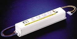
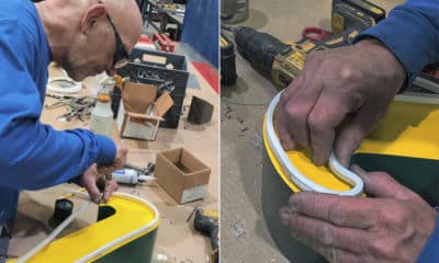
Ballasts should be tested to avoid unnecessary replacements. (Photo courtesy of Magnetek, Nashville, TN).
My father-in-law was a master sheet-metal mechanic whose lifelong hobby was fixing cars. Ralph described contemporary auto mechanics as “parts replacers.” He often complained, “They replace parts instead of checking to see what’s wrong.”
Ralph’s Law explains why it’s now customary to take your car back to “Mr. Badwrench” three or more times to correct a single problem. It also explains why many sign ballasts returned to suppliers as “defective” still work perfectly. To save yourself and your customers unnecessary grief and expense, it’s important to know how to diagnose ballast problems.
I frequently see messages posted in the SignWeb message boards soliciting help in determining why a particular electric sign won’t work. Although the image of laptop-wielding sign mechanics is a bit scary, the urgency of certain messages implies novice sign repairmen are awaiting instructions inside customers’ stores. Therefore, it’s worthwhile to take a closer look at testing and installation of fluorescent sign ballasts.
The old school
Even guys like Ralph, who wouldn’t be caught dead carrying a copy of War and Peace, realize the importance of written instructions. For some inscrutable, genetic reason, however, most males believe repairing things by intuition is a sign of virility. It’s not uncommon, therefore, to hear old-timers claim they can test ballasts using a variety of unconventional methods. Although some of these tricks might work, it’s better to use a formal diagnostic procedure.
AdvertisementSometimes, however, there’s no need for extensive troubleshooting. Some lighting problems are obvious as soon as the sign is opened. Other faults can be located by tugging on secondary wires or twisting lamps gently back and forth in their sockets. If the ballast trips a circuit breaker and leaks black potting compound profusely from its seams, it’s probably defective. Because defective ballasts generate higher-than-normal temperatures, the paint on the outside of the casing might be blistered or discolored. Sometimes an internal short will burn a visible hole through the ballast case.
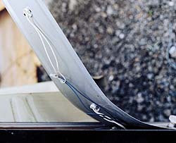
If you see blackened lamp sockets, hear arcing electricity or smell the odor of burned wiring when you open the sign, don’t bother testing. Remove all the lamps and open the raceway covers to inspect the sockets and secondary wiring (Fig. 1). This is particularly true when the socket raceway is located on the bottom of the sign where water collects.
By the book
Although seeing, hearing and smelling can locate certain problems, electrical faults are often hidden. Signs may be designed in ways that make it difficult to inspect the secondary wires, or faults may exist inside the ballast. In these cases, you must test the system to determine the source of the problem before replacing the ballast.
First, however, let’s review how ballasts operate. A high-output (HO) sign ballast is designed to operate a sequential series-circuit. The lamps start in a sequence beginning with the lamp or lamp pair closest to ground potential, and culminating with the lamp connected to the high side of the ballast secondary (commonly designated by the color red). Lamps start in a sequence corresponding to the order in which they are numbered on the ballast’s wiring diagram.
To test any ballast, begin by checking the primary input voltage with the lamps and ballasts connected to the circuit. Low voltage caused by overloads or undersized feed wires is the most common problem. But the voltage drop won’t show up on your voltmeter unless the sign is connected when you test. For 120-volt signs, the tested voltage should be 115-125 volts. If you notice that the insulated, primary wires are very warm or hot to the touch, the wiring is probably too small for the connected load.
AdvertisementOnce you’ve confirmed the primary voltage is adequate, check for proper grounding of the metal sign cabinet by measuring for voltage between the grounded conductor (white) and the cabinet. If any significant voltage is present, the cabinet is not properly grounded. In this case, it should not be used as a substitute for the grounded conductor when testing. Because ungrounded signs are hazardous and troublesome, this problem should be corrected as part of the repair.
Test procedure 1
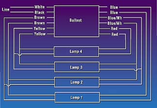
Ballast failures fall into two main categories. In the first category none of the lamps on the ballast circuit are working. Let’s examine testing procedures for this situation, using a typical three-lamp, HO ballast (Fig. 2).
In this case, if the primary voltage is adequate, you must first test the ballast’s open circuit voltage (OCV). To avoid damaging your voltmeter, set the selector dial to the proper scale for the OCV indicated on the ballast label. Then, connect one meter-probe to one of the red ballast leads, and connect the other meter-probe to the grounded conductor (white wire).
If your initial OCV test reads at or near zero, turn off the power and cut off both red leads six inches from the ballast case. If you read normal voltage when you test these disconnected leads, the ballast is OK, but you have a fault in the red wires running to the socket, or in the socket itself. Conversely, if the OCV reading is still not correct with the red leads disconnected, the ballast is defective.
If you read proper voltage at the red socket, however, the ballast could have a faulty internal starting capacitor. Test this by measuring the voltage-to-ground at the high side of the No. 1 lamp. Connect one of the meter-probes to a blue/white wire and the other to the grounded conductor. If your voltage reading is at or near zero, the capacitor is faulty, and you must replace the ballast. If, however, you read voltage only slightly less than the level measured at the red lead, the starting capacitor is working properly. In this case, you have an open circuit on the low side of No. 1 lamp (blue wires). If the blue wires are not faulty, the ballast has an internal fault and must be replaced.
AdvertisementTo make a quick test, turn off the power; cut off one of the blue leads at a point approximately six inches from the ballast case; connect a jumper wire from this lead to the grounded conductor; and turn the power on. If the lamps now light up, you have an open circuit inside the ballast. Remember that this is only a temporary testing measure, and the jumper should be removed immediately after testing.
Test procedure 2
The second category covers ballast failures in which some lamps light but others do not. Using Fig. 2, suppose that lamps No. 1 and No. 2 are lighted, but No. 3 is out. After first checking the primary voltage and cabinet grounding, test the OCV by measuring between one red lead and the grounded conductor. If the voltage is higher than normal, check the next lead in the series circuit (yellow wire). If you still get the same voltage reading, an internal capacitor (“B” in Fig. 2) is defective and the ballast must be replaced.
Continuing through the lamp series, if you read approximately the same voltage when testing a blue/white lead as you found at the red lead, the other internal capacitor (“A” in Fig. 2) is shorted and the ballast must be replaced. Note that testing always proceeds inversely to the lamp numbers, beginning with the red No. 3 leads and ending with the No. 1 lamp leads. If your test indicates zero or very low voltage at the yellow or blue-white leads, it indicates a fault in the corresponding wires or sockets.
Filament testing
Rapid-start ballasts (including sign ballasts) incorporate separate, internal heater windings that continuously heat the lamp cathodes. If a heater circuit is faulty, lamps may start intermittently, depending on environmental conditions. Lamps operated without filament heating typically fail rapidly (several hours to a few days).
A telltale sign of a defective heater circuit is a single lamp or two adjacent lamps that do not light in a series where all the other lamps appear to be in good condition. If you inspect one of the problem lamps, you will notice a dark band 2-5 inches from one end, but the opposite end appears normal. This contrasts with the appearance of old lamps that blacken uniformly on both ends.
To test for proper filament voltage, measure across the socket contacts. The voltage should be 3.4-3.9 volts. Ballast manufactuers suggest using a filament tester to check sockets. This device resembles the cut-off end of a fluorescent lamp, and it’s designed to light up brightly when the filament voltage is adequate.
If you find low or absent voltage, a fault might exist between the socket and the ballast. With the power off, cut both leads to this socket approximately six inches from where they enter the ballast case. Then, connect the voltmeter probes and turn on the power. If the voltage doesn’t fall in the 3.4 to 3.9-volt range (typically, the reading will be very low or zero), the ballast is defective.
Installation
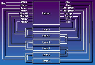
These methods are also suitable to test four- and six-lamp sign ballasts (Figs. 3 and 4). Each ballast is designed to operate a specific minimum and maximum length of lamps. For example, the ballast’s label may indicate that that it operates three or four lamps with a total lamp length of 20-32 feet. Thus, the maximum capacity of this ballast is four 8-foot HO lamps. Never attempt to operate a longer or shorter lamp footage than the range specified on the ballast.
Ballasts are available that operate a wide range of lamp numbers and lengths. It’s advisable for service mechanics to carry some of these “universal ballasts” to deal with unexpected situations. Except in a pinch, however, it’s not cost-effective to use a larger ballast than you need. Also, the larger ballast probably won’t fit in place of the old ballast without making some alterations.
Always bolt the ballast securely inside the sign cabinet with its bottom flush against the metal mounting surface. For proper heat dispersion, no air gap should exist between the bottom of the ballast and the mounting surface. Ballasts should not be installed on the bottoms of outdoor sign cabinets where water collects. If a ballast is mounted vertically, the ballast wires on its top end should be coiled in “drip loops” to prevent water from “wicking” down into the ballast case.
To provide your customers with professional service, your service people can’t merely be “parts replacers.” Give them the training and tools to diagnose lighting problems before performing unnecessary work.
Dealing with UL 2161
The following information was provided in the May 4, 1999, California Electric Sign Assn. (CESA) “Member Alert”:
Any Authority Having Jurisdiction (AHJ) that has adopted the 1996 National Electrical Code (NEC) can now enforce the UL 2161 requirements for neon transformers. Sign companies and their customers should be aware of the following ramifications:
1) UL 2161 transformers cost approximately twice as much as the old-style transformers.
2) Existing signs may contain some UL 2161 units and some old-style units. This could confuse service mechanics when troubleshooting signs.
3) If an existing sign has metal conduits too long (more than 20 feet) or inadequate spacing of live parts to metal, rewiring the entire sign might be necessary for UL 2161 transformers to operate.
4) Previous testing methods such as grounding the transformer’s secondary to the T-box, or using jumper wires to test neon tubes will cause UL 2161 units to trip. Old-style transformers should be carried on all service trucks for troubleshooting purposes, and neon tube testers should be used instead of jumper wires.
5) Effective September 3, 1999, all new neon signs must incorporate UL 2161-compliant transformers.
6) Transformers rated at 30mA or less and 3000 volts-to-ground or less (6,000/30mA) do not require secondary ground fault protection (SGFP) under UL 2161 regulations. PBKM transformers used in channel letters with no GTO wires also do not require SGFP devices.

Introducing the Sign Industry Podcast
The Sign Industry Podcast is a platform for every sign person out there — from the old-timers who bent neon and hand-lettered boats to those venturing into new technologies — we want to get their stories out for everyone to hear. Come join us and listen to stories, learn tricks or techniques, and get insights of what’s to come. We are the world’s second oldest profession. The folks who started the world’s oldest profession needed a sign.


Magazine
Get the most important news
and business ideas from Signsofthetimes Magazine.
-

 Tip Sheet3 days ago
Always Brand Yourself and Wear Fewer Hats — Two of April’s Sign Tips
-

 Business Management2 weeks ago
When Should Sign Companies Hire Salespeople or Fire Customers?
-

 Women in Signs2 weeks ago
2024 Women in Signs Award Winners Excel in Diverse Roles
-

 Real Deal4 days ago
A Woman Sign Company Owner Confronts a Sexist Wholesaler
-

 Editor's Note1 week ago
Why We Still Need the Women in Signs Award
-

 Benchmarks13 hours ago
6 Sports Venue Signs Deserving a Standing Ovation
-

 Line Time2 weeks ago
One Less Thing to Do for Sign Customers
-

 Product Buying + Technology1 week ago
ADA Signs and More Uses for Engraving Machines