Last month (page 26), I compared the special demands fluorescent lamps’ electronic control gear to well-known magnetic ballasts’ requirements. Large sign projects that include projected signs often require adjustable light levels to avoid “light pollution” or other neighborhood issues. Architectural-lighting applications often mandate lamp dimming.
Dimming cold-cathode or neon tubing is rather simple if installers observe a few facts (see ST, June 2005, page 20). Let’s first examine how fluorescent dimming works.
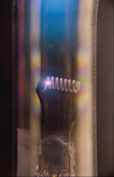
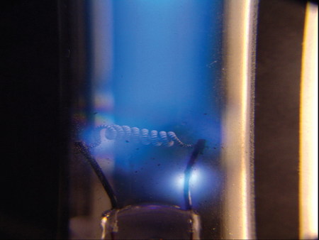
Electrode construction and operation differentiates cold-cathode and fluorescent lamps. A fluorescent-lamp electrode must reach a minimum temperature to release electrons into the gas. In normal lamp operation, ions bombard the electrode to heat it. Ion impingement maximizes at the hottest part of the electrode, the electron-emission point, thus forming a “hot spot.” Only a small part of the electrode surface carries the lamp's operating current.
If an electrode hasn’t reached operating temperature, and isn’t ready to emit electrons thermally, and if high voltage is applied to force a current through the lamp (the scenario for “instant start”), the operates similarly to a cold-cathode electrode.
As Georges Claude’s first neon patent claimed in 1910, a cold-cathode electrode can carry only a limited amount of current per surface, or it will be destroyed by sputtering very quickly, and the maximum load was 6.5mA per square centimeter of electrode surface.
A fluorescent lamp electrode has a small surface compared to the current, and if it operates like a cold-cathode electrode, sputtering will destroy it quickly, even when the lamp operates at reduced current.
Advertisement
Dimming a neon lamp is achieved by reducing the effective (average) operating current flowing through the lamp. This also applies to dimming a fluorescent lamp, but there’s a problem: When the ion current that’s heating the electrode to the proper operating temperature drops, the electrode won’t be kept at the temperature needed to emit electrons and will act as a cold-cathode electrode. Below a certain current level, sputtering will destroy it. To overcome this problem, the electrode must always be maintained at operating temperature.
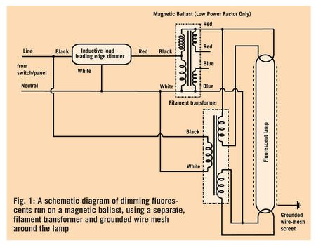
Here’s the classic solution: Use a separate heating transformer, which is powered continuously, whereas the dimmer controls the current to the gas discharge via the magnetic ballast. If a magnetic ballast is used with leading-edge, phase-cut dimmers, the lamp is ignited every half cycle, like a neon tube running on AC. To prevent flickering caused by uneven starts, the lamp is sleeved with a grounded wire mesh. High-power-factor ballasts can’t be used.
In this circuit, constant power heats the electrodes, which is a big disadvantage. Thus, when the lamp runs on high current, the ion-impact heat, plus the filament heat, can lead to an overheated electrode and reduce lamp life by evaporating cathode material.
Modern, intelligent, electronic ballasts apply a tube current and, simultaneously, heating power to the filaments, and reduce the heating power when the lamp current increases. Consequently, the electrode maintains the correct operating temperature at every lamp-current setting. Also, before lamp start, they apply only heating current to bring the electrodes up to operating temperature.
As with neon tubes, to sustain the gas discharge, fluorescent lamps must receive at least a minimum current flow and can’t be dimmed to zero intensity. You either must maintain at least minimum intensity or switch it off completely.
Different controls
Advertisement
Systems that use magnetic ballasts can be dimmed with standard leading-edge, phase-cut dimmers designed for inductive loads (same as those used for A/C motors and neon signs). Therefore, controlling these systems depends on the external dimmer control – a knob or electric signal. Electronic ballasts now employ different controls, but all controls directly affect electronic oscillator output. (For a similar overview on neon dimmers, see the previously cited, June 2005 column.)
The most frequently used lighting-application system is the 0-10V control, in which a low-voltage, DC signal varies from zero (lamp off/minimum brightness) to 10V (maximum brightness). This system allows one controller to control many ballasts by connecting all control inputs together in parallel. Observe correct polarity with DC circuits – or damage may result.
To use the same electronic ballast with elaborate dimmer controls, or, as well, with very cheap, simple controls, the 0- to 10V dimming standard dictates the ballast must check the voltage applied to the control terminals and also supply the control voltage. How does this work?
The ballast is sourcing control power at high resistance. Thus, in extreme cases, with no control unit connected (open-control input), the built-in DC supply pulls the input terminal to 10V, and the ballast runs the lamp at maximum intensity. When the control terminals are shorted, the ballasts sense 0V; a small current (approximately less than 1mA) flows through the shorting wire, and the lamp dims as much as possible.
The simplest control for such ballasts, a variable resistor, changes linear from open (or more than 10,000 ohms) for the complete control range. After installation or service, a trimming resistor can set a sign’s brightness once. For more elaborate systems, electronic dimmers will control the voltage at the output terminals leading to the ballast(s).
Advertisement
When connecting multiple ballasts to one variable resistor, keep in mind every ballast emits current to the control line, which must be absorbed by the resistor. Thus, the resistance for a single ballast, in a circuit of number (n) of equal ballasts, connected together, is 1/n. Using 10,000 ohms as our example, this would be 5,000 ohms, or 10,000/2 for two ballasts, or 1,000 ohms for 10 ballasts on the same control resistor.
In digital standards, the “intelligent” ballast receives a digital, control-word signal via a serial network cable; the data signal is daisy-chained from one ballast to the next. Two data protocols are commonly used. In the DMX protocol, which emerged from stage-lighting systems, each ballast has an individual address and can be set in 256 intensity steps. The other common protocol, DALI, stems from large-building, HVAC control systems.
I don’t have enough space in this column to cover all dimming-system substandards and accesso¬ries, such as protocol/system converters. Control software alone could fill pages, so carefully check if all components you’re using are compatible.
I’ve seen such weird, fluorescent-dimming systems as company-specific units that use the 0-10V inversely and as draining inputs, or “dimmable” systems that range only from 100 to 80% intensity. I can only recommend you check if the product you’re specifying will meet the dimmer standard you selected and the customer’s requirements, so you won’t be surprised when you switch on the installation the first time.
Marcus Thielen is a physicist and neon consultant from Duisburg, Germany.


 Tip Sheet3 days ago
 Business Management1 week ago
 Women in Signs2 weeks ago
 Real Deal4 days ago
 Editor's Note1 week ago
 Maggie Harlow2 weeks ago
 Line Time2 weeks ago
 Product Buying + Technology1 week ago